


EIFS Drainage-Plane Failures in Commercial Construction: Why the Mat and the Termination Are Where Cases Are Won and Lost
Probe testing on a four-story mixed-use building in Charlotte, North Carolina told a familiar story. The building was three years old.
- EIFS Drainage-Plane Failures in Commercial Construction: Why the Mat and the Termination Are Where Cases Are Won and Lost
- Why Drainage-Plane EIFS Was Supposed to Solve the Water Problem
- How ASTM E2568 Defines Drainage Efficiency and What the Updated Provisions Now Require
- Drainage Mat Selection: The Variable Most Often Underspecified
- Termination Detailing: Where Drainage Plane Failures Concentrate
- WRB Integration Failures at Penetrations: The Hidden Multiplier
- Field Inspection Protocols That Actually Catch These Failures
- What the Next Project Specification Should Require
The EIFS finish coat was intact, the EPS board showed no delamination and the base coat mesh was continuous. Infrared thermography during a wet weather event confirmed widespread interstitial moisture accumulation behind the cladding across the lower third of every elevation.
The specification had called for a drainage-plane assembly. The drainage mat had been compressed to near-zero void space at base-of-wall terminations under adhesive pressure and mechanical fastener bearing loads.
Water entered the assembly, found no functional drainage path and sat against the WRB. The finish coat did not fail.
The drainage plane did.
Why Drainage-Plane EIFS Was Supposed to Solve the Water Problem
The industry’s shift from barrier EIFS to drainage-plane EIFS was not voluntary. It followed a decade of catastrophic moisture litigation concentrated in the Southeast and Mid-Atlantic, where barrier assemblies performed as designed until any single penetration seal failed, at which point there was no secondary drainage path and substrate damage was inevitable.
Drainage-plane EIFS introduced a capillary break between the EPS board and the WRB, creating a gravity-driven drainage path that was supposed to intercept incidental water and route it to an open termination at the base of the assembly.
That design intent is sound. According to EIMA market data, drainage-plane EIFS now dominates commercial specifications across mixed-humid IECC Climate Zones 3 and 4 and cold Climate Zones 5 through 7. The problem is not the concept.
The problem is that field execution consistently fails to realize the drainage capacity that laboratory testing demonstrates and the gap between specification language and installed performance is where moisture damage accumulates.
ASTM E2568 provides the foundational standard for PB EIFS, including drainage efficiency requirements. The standard exists precisely because the industry recognized that specifying “drainage-plane EIFS” without measurable performance criteria produced assemblies that looked correct on paper and failed in service.
That recognition came at significant cost. The litigation wave that preceded the standard’s drainage provisions generated hundreds of millions of dollars in remediation claims on mid-rise residential and commercial buildings across North Carolina, Virginia and Maryland alone.
Those buildings were not constructed with defective materials. They were constructed with barrier EIFS installed correctly and the correct installation of a barrier system was still insufficient once a sealant joint at a window corner or a pipe penetration lost adhesion.
The entire cladding assembly then became a moisture trap with no exit path. Drainage-plane EIFS was the industry’s response to that structural vulnerability and ASTM E2568 was the mechanism for ensuring that the response had measurable teeth rather than just marketing language.
How ASTM E2568 Defines Drainage Efficiency and What the Updated Provisions Now Require
ASTM E2568 Section 7 establishes a minimum 90% drainage efficiency threshold for drainage-plane EIFS systems. The test protocol introduces a defined volume of water at the top of a test assembly and measures the volume recovered at the base termination.
A system that retains more than 10% of introduced water fails the threshold. The measurement is straightforward.
The interpretation requires care.
Recent updates to E2568 require manufacturers to document drainage efficiency by specific mat type and thickness. This matters because specifiers can no longer write “drainage-plane EIFS per ASTM E2568” and assume the specified system meets the threshold.
Product-specific documentation is now required and that documentation must accompany submittals.
The harder problem is that bench testing does not capture field-installed conditions. The E2568 drainage efficiency test uses a uniformly applied mat with clean terminations under controlled conditions.
It does not account for adhesive coverage patterns that compress mat void space, mechanical fastener bearing loads at base track attachments or the geometry of field-cut terminations at penetrations. A mat that achieves 94% drainage efficiency in the laboratory can perform at a fraction of that in service.
The practical implication for specifications is direct: project specifications must explicitly reference drainage efficiency documentation by product designation, not just invoke the standard generically. The EIMA Technical Bulletin on drainage mat documentation provides companion guidance on what that submittal package should contain.
Specifiers who skip this step are accepting undocumented drainage performance.
What that gap between laboratory and field performance looks like in practice is worth examining in detail. Adhesive applied at 40% coverage, which is within the range of typical field application, can reduce effective mat void space by 30% or more at contact points.
When the EPS board is pressed against the adhesive, the mat compresses unevenly across the field of the wall. The E2568 test assembly does not replicate that pressure distribution because the test is designed to evaluate the mat product, not the installation method.
The standard is doing what it was designed to do. The problem is that specifiers treat the standard as a proxy for installed performance rather than as a product qualification floor.
A specification that requires E2568 compliance without also requiring installation method controls, adhesive coverage limits and photographic documentation of mat condition before concealment is a specification that stops short of controlling the outcome it is meant to guarantee. ICC-ES Acceptance Criteria AC219 provides additional product evaluation requirements for drainage-plane EIFS components that can supplement E2568 documentation in submittal packages and specifiers working on projects with elevated moisture risk should consider requiring both.
Drainage Mat Selection: The Variable Most Often Underspecified
Three primary drainage mat configurations appear in commercial EIFS practice: entangled polymer mesh mats, grooved EPS board and fabric-faced drainage composites. Each has a distinct void ratio, compressive resistance profile and drainage path geometry.
Treating them as interchangeable is a specification error that produces predictable field failures.
Compressive resistance is the critical selection criterion that most specifiers ignore. Entangled mesh mats with low compressive resistance lose void space under adhesive pressure during EPS board attachment.
At mechanical fastener locations, point loads compress the mat to near-zero void space locally, creating discrete zones with no drainage capacity. If those zones concentrate at base-of-wall terminations, where drainage demand is highest, the assembly fails at the most consequential location.
Compressive resistance per ASTM D1621 should be a required submittal item for any drainage mat specified on a commercial project. It rarely is.
Climate-specific selection adds another layer. In IECC Climate Zones 5 through 7, drainage mats must maintain void space through freeze-thaw cycling.
A mat that traps liquid water in low-slope base-of-wall geometry during a freeze event can develop ice lens formation that mechanically deforms the termination detail, compromises the weep screed seal and creates a new water entry path. This failure mode is not hypothetical.
It shows up in forensic investigations on institutional buildings in the upper Midwest with regularity.
The specifier failure pattern is consistent: mat selection is delegated entirely to the EIFS manufacturer’s standard system package without evaluating whether the default mat meets project-specific drainage demands driven by wall height, climate zone and cladding weight. The ASTM E2568 drainage efficiency threshold is the benchmark for verification.
The ASHRAE 90.1-2022 climate zone map provides the framework for climate-specific selection rationale. Neither gets invoked when mat selection is treated as a manufacturer’s prerogative rather than a specifier’s decision.
The void ratio differences between mat types are not trivial. Entangled polymer mesh mats typically offer nominal void ratios in the range of 75% to 85% before installation loads are applied.
Grooved EPS board products offer a defined channel geometry that is more resistant to compression under adhesive pressure but provides a less tortuous drainage path, which affects drainage efficiency at low flow rates. Fabric-faced drainage composites introduce a filtration layer that resists fine particle migration into the drainage plane but adds a capillary retention component that can reduce drainage efficiency in fine-gap geometries.
Each of these tradeoffs has direct implications for the project’s climate zone, wall height and expected moisture load. A four-story building in Charlotte with a high window-to-wall ratio generates a different drainage demand profile than a two-story retail building in Minneapolis with minimal fenestration.
Specifying the same default mat for both projects because the manufacturer’s standard system package includes it is not a specification decision. It is an abdication of one.
The EIMA Technical Bulletin series on drainage mat performance provides product-category guidance that gives specifiers a starting framework for making this selection on a defensible technical basis rather than defaulting to whatever the manufacturer’s representative recommends at the pre-bid meeting.
Termination Detailing: Where Drainage Plane Failures Concentrate
Base-of-wall termination is the highest-risk location in any drainage-plane EIFS assembly. The drainage mat must transition to a weep screed or open termination that allows water to exit without re-entry.
Compression of the mat at screed attachment is the most common failure mechanism in forensic investigations and it is almost always the result of installation sequence: the screed is attached first, the mat is run into the screed pocket and the EPS board is pressed against the assembly, compressing the mat at the exact location where drainage capacity is most needed.
Window and door head terminations represent the second highest concentration of failures. The drainage mat must be cut and terminated at opening headers with a positive slope directing water to the face of the WRB and out through flashing.
When this step is omitted, water accumulates at the horizontal termination line, saturates the mat edge and migrates laterally behind the EPS board. ASTM E2112 provides the reference standard for fenestration installation coordination; the termination of the drainage mat at opening headers must be explicitly coordinated with the flashing sequence described in that standard.
Penetration terminations are where the drainage plane is most casually abandoned. Pipes, conduit and structural attachments require the mat to be cut and fitted around the penetration sleeve.
In field practice, the mat is cut and butted against the sleeve without sealing the mat edge to the WRB, creating a lateral water migration path behind the mat rather than a vertical drainage path through it. The water control layer is compromised and the drainage plane is locally bypassed.
Roof-to-wall and deck-to-wall transitions require drainage mat termination coordinated with through-wall flashing. IBC Chapter 14 establishes cladding termination and flashing requirements at horizontal interruptions.
EIFS shop drawings routinely omit this coordination detail and submittal reviewers routinely miss it. The EIMA Guideline Specification addresses base termination requirements explicitly; that document should be a required reference in the specification section, not an optional resource.
The installation sequence problem at base-of-wall terminations deserves more attention than it typically receives in pre-construction meetings. The correct sequence requires the drainage mat to be terminated at the weep screed with enough clearance that EPS board attachment pressure does not close the mat’s void space at the screed throat.
In practice, this means the mat must be cut to terminate at the back face of the screed flange rather than being tucked into the screed pocket. When the mat is tucked into the pocket, EPS board pressure against the screed face compresses the mat against the screed’s back wall and the drainage path closes.
The water that reaches the base of the assembly has nowhere to go except laterally along the screed track or back into the mat. Neither outcome is acceptable.
This sequence error is not a training failure on the part of individual installers. It is a specification and shop drawing failure.
If the termination sequence is not shown explicitly on the EIFS shop drawings and called out in the specification’s installation requirements, the installer will default to whatever sequence is fastest. That sequence is almost always the one that produces the compression failure.
Requiring the EIFS subcontractor to submit a written installation sequence narrative for base-of-wall terminations as part of the submittal package, reviewed and approved before installation begins, is a low-friction intervention that catches this failure mode before it is built into the wall.
WRB Integration Failures at Penetrations: The Hidden Multiplier
The drainage mat and WRB function as a system. A properly selected and terminated mat cannot compensate for WRB laps, seams or penetration seals that allow water to bypass the drainage plane entirely and contact the substrate directly.
When both the drainage mat and the WRB fail at the same location, moisture damage is not additive. It is compounding.
The most common WRB failure at penetrations is an unsealed lap at a penetration sleeve where the WRB has been cut, wrapped around the sleeve and left without sealant at the termination edge. Water that bypasses the drainage mat at that location contacts the substrate without any secondary interception.
The drainage plane offers no protection because the water is already behind it.
Fluid-applied WRBs perform better at complex penetration geometry than sheet-applied products, but they introduce their own failure mode: inadequate mil thickness at inside corners and around fastener heads. ASTM E2357 testing demonstrates air and water resistance at the assembly level, but field-applied fluid membranes are thickness-dependent and thickness is rarely verified in the field.
The four control layers (water, air, vapor and thermal) must each be continuous to function. A WRB with pinhole defects at penetrations fails the water control layer regardless of drainage mat performance above it.
The compounding failure dynamic is what makes WRB integration the hidden multiplier in drainage-plane EIFS forensic investigations. A drainage mat that is performing at 85% efficiency, below the E2568 threshold but not catastrophically so, can still manage incidental water infiltration at most wall locations if the WRB is continuous and properly lapped.
The substrate stays dry because the WRB is intercepting what the mat misses. When the WRB also fails at a penetration, the mat’s reduced drainage efficiency at that location means water is both bypassing the drainage plane and finding no secondary interception at the WRB.
The substrate at that location sees the full moisture load with no functional control layer between the water and the framing. This is the failure pattern that produces the worst substrate damage in forensic investigations and it is the pattern that appears most frequently at mechanical penetrations, structural bracket attachments and window rough openings where both the mat and the WRB have been cut and neither has been properly reinstated.
ICC-ES AC71 provides evaluation criteria for fluid-applied WRB products that can inform product selection for complex penetration geometry. Specifying a fluid-applied WRB product that meets AC71 criteria and requiring wet mil thickness verification at penetrations and inside corners during installation inspection addresses the most common fluid-applied failure modes before they are concealed.
Sheet-applied WRB products require explicit lap width and sealant requirements at penetration sleeves to be called out in the specification, because the default installation practice in most markets does not include sealant at sleeve terminations unless the specification requires it.
Field Inspection Protocols That Actually Catch These Failures
Specifying the correct drainage mat and detailing the terminations correctly on paper is necessary but not sufficient. Failures in the Charlotte building described above were entirely preventable with a targeted inspection protocol at three specific milestones: after WRB installation and before EPS board attachment, after EPS board attachment and before base coat application and after base coat application at termination locations accessible for probe testing.
Most project inspection protocols do not include these milestones explicitly. The WRB is inspected as part of the rough-in phase, the EIFS is inspected as part of the exterior cladding phase and the gap between them, where drainage mat compression and termination failures occur, receives no dedicated attention.
This is a scheduling and specification problem, not a materials problem.
Requiring the EIFS subcontractor to submit photographic documentation of drainage mat installation at base-of-wall terminations, fenestration headers and penetration locations before EPS board covers the work is a low-cost quality control measure that catches the majority of termination failures before they are inaccessible. It is also a contractual mechanism that shifts documentation responsibility to the party with direct installation knowledge.
The three-milestone inspection framework maps directly to the failure modes described throughout this article. The first milestone, after WRB installation and before EPS board attachment, is the only opportunity to verify WRB lap dimensions, sealant application at penetration sleeves and fluid-applied membrane thickness at inside corners and fastener heads.
Once the EPS board is attached, none of those conditions are accessible without destructive investigation. The second milestone, after EPS board attachment and before base coat application, is the opportunity to verify that drainage mat compression has not occurred at base-of-wall terminations and that the mat has been properly cut and terminated at fenestration headers and penetrations.
A visual inspection at this stage requires only that the inspector know what a properly terminated mat looks like at each condition, which means the inspection checklist must include photographs of correct and incorrect termination conditions as reference standards. The third milestone, after base coat application at accessible termination locations, allows probe testing at weep screed locations to verify that drainage paths are open and that water introduced above the screed exits at the screed face rather than accumulating behind the assembly.
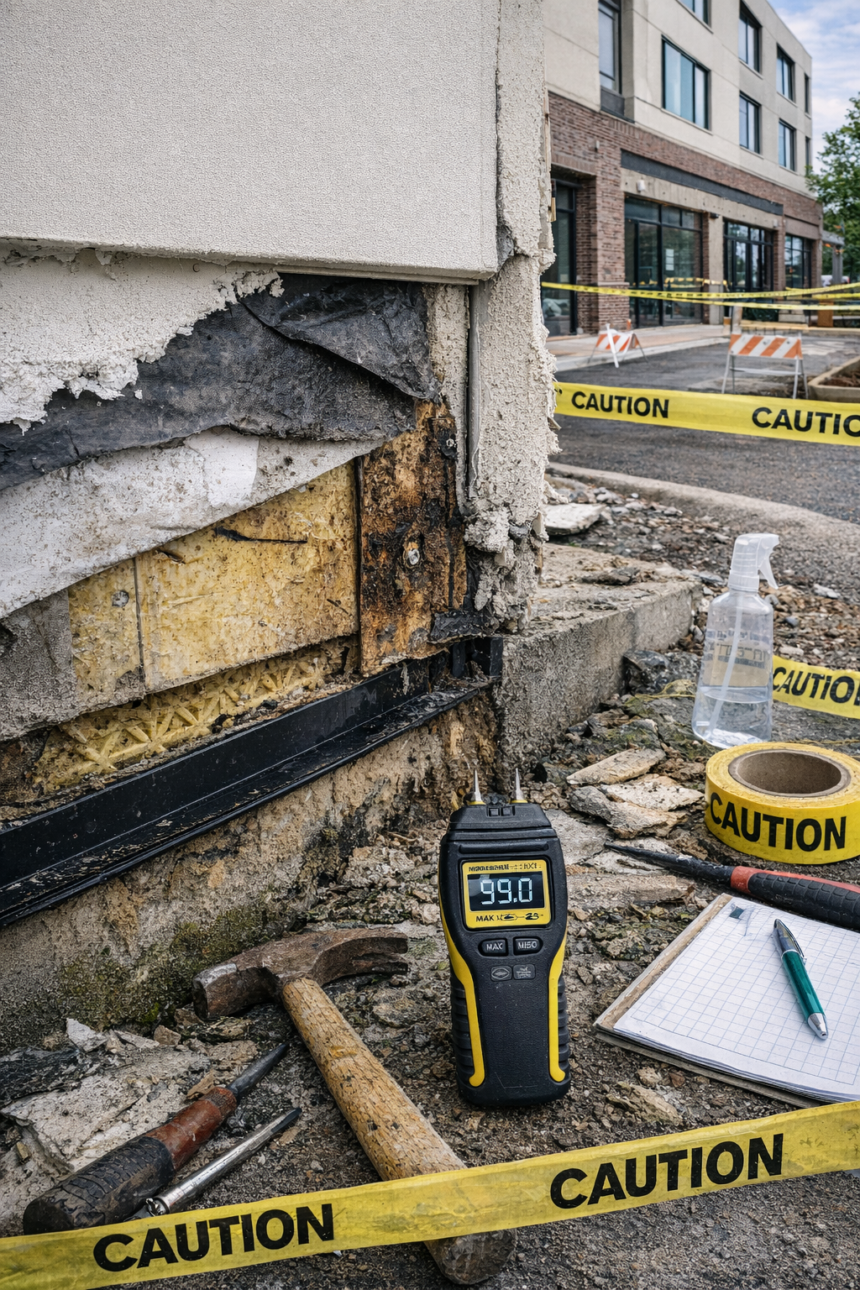
This test takes approximately 20 minutes per elevation and requires a garden sprayer and a moisture meter. It is not a sophisticated diagnostic.
It is a functional verification that the drainage plane is working as specified. The fact that this test is almost never performed on commercial projects before the finish coat is applied is not a reflection of its difficulty.
It is a reflection of the fact that no one has written it into the inspection protocol and assigned it to a responsible party with a contractual obligation to perform it. Specifying these three milestones in Division 07 of the project manual, assigning inspection responsibility to the special inspector of record and requiring photographic documentation submittals within 48 hours of each milestone creates an inspection record that either confirms correct installation or identifies failures while correction is still practical.
What the Next Project Specification Should Require
The drainage-plane EIFS failures that generate litigation in North America are not random. They concentrate at the same locations, result from the same