Curtainwall Condensation Failures in High-Performance Buildings: The Physics We Keep Ignoring
Introduction: When Better Envelopes Create New Failure Modes
As buildings push toward net-zero energy targets, envelope assemblies are getting tighter, better insulated, and more thermally optimized than ever before. Opaque wall assemblies routinely achieve high effective R-values with continuous insulation and minimized thermal bridges. Air leakage targets are stricter. Interior humidity is more stable.
Yet in many high-performance projects, condensation is appearing inside curtainwall systems—on mullion interiors, within glazing pockets, and sometimes even inside pressure plates and covers.
The common reaction is to question the glass specification or the air barrier continuity. But in many cases, the real issue is more basic: localized thermal bridges in curtainwall framing that were always present—but are now more consequential.
As glazing ratios increase and opaque walls improve, the curtainwall becomes the weak link in otherwise robust assemblies. The physics has not changed. The boundary conditions have.
For facade engineers and building science consultants, understanding why condensation forms inside curtainwall systems is no longer optional. It is central to risk management.
Why Condensation Is Showing Up More Frequently
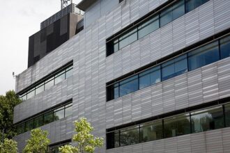
1. Higher Glazing Ratios Mean More Framing Exposure
Contemporary commercial buildings routinely push glazing ratios of 60–80%. Even when high-performance IGUs are specified, the aluminum framing remains a dominant thermal bridge.
Unlike opaque walls with continuous insulation, most curtainwall systems rely on internal polyamide thermal breaks and pocketed insulation. These improve center-of-frame performance, but they do not eliminate three-dimensional heat flow at:
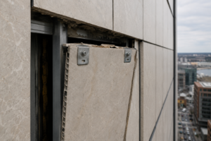
- Anchor brackets
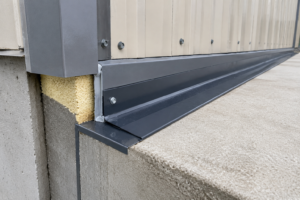
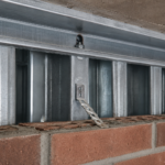
- Slab edge transitions
- Mullion intersections
- Spandrel backpans
- Pressure plate fasteners
When glazing area increases, the aggregate impact of these localized bridges increases with it.
2. Tighter Buildings Raise Interior Humidity
Net-zero and high-performance buildings emphasize air tightness. Infiltration decreases, and mechanical ventilation becomes the primary driver of moisture removal.
In mixed climates—where heating and cooling seasons both matter—interior relative humidity often remains between 35–45% during winter. That may sound modest, but at typical indoor temperatures, this creates a dew point in the mid-40s °F.
If any interior-facing metal surface within the curtainwall drops below that temperature, condensation becomes inevitable.
The key shift is this: we have improved opaque assemblies so much that the curtainwall frame now represents the coldest interior surface in the building.
The Physics: Surface Temperature, Not Glass U-Value
When condensation appears on curtainwall components, design teams often look first at the glazing U-value. But condensation risk is governed by surface temperature relative to dew point—not just overall assembly U-value.
The critical factors are:
- Interior air temperature
- Interior relative humidity
- Exterior temperature
- Localized thermal conductivity paths
Aluminum framing conducts heat efficiently. Even with thermal breaks, interior aluminum surfaces near anchors or intersections can drop well below the average frame temperature predicted by simplified calculations.
Two-dimensional and three-dimensional heat flow modeling often reveals what one-dimensional U-value calculations conceal:
- Frame corners are colder than mid-span mullions.
- Anchors can act as concentrated heat sinks.
- Slab edge conditions introduce significant thermal discontinuities.
If the interior surface temperature of a mullion drops below the dew point, condensation forms—regardless of the IGU center-of-glass performance.
Why Mixed Climates Are Particularly Vulnerable
In purely cold climates, interior humidity is often actively managed to avoid window condensation. In warm-humid climates, condensation risk is frequently associated with inward vapor drive during cooling seasons.
Mixed climates create a more complex scenario:
- Winter heating produces interior-to-exterior vapor drive.
- Shoulder seasons can include rapid temperature swings.
- High-performance envelopes maintain interior humidity levels that were previously moderated by leakage.
In these environments, small thermal discontinuities become critical. A detail that might have been benign in a leaky building now produces visible moisture in a tight one.
This is especially relevant in cities such as Boston, Chicago, and New York City, where winter heating loads are significant but buildings also experience humid summers.
Where Condensation Typically Forms Inside Curtainwalls
Field investigations repeatedly show moisture at predictable locations:
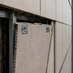
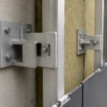
1. Interior Mullion Faces Near Anchors
Steel embeds and aluminum anchors create thermal bypasses around thermal breaks. Localized surface temperatures can drop 5–10°F below adjacent framing.
2. Glazing Pockets and Gaskets
Even when interior surfaces appear dry, condensation may form inside glazing pockets where air is trapped and temperature gradients are sharper.
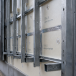
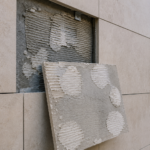
3. Spandrel Zones
Backpans and perimeter framing near slab edges are common condensation points, particularly where insulation continuity is interrupted.
4. Pressure Plates and Fasteners
Fasteners penetrate thermal breaks. While individually small, their cumulative effect can create measurable surface temperature reductions.
The visible symptom may be water staining or corrosion on interior trim. The root cause is almost always localized heat flow.
The Modeling Gap: What We Underestimate
Most curtainwall performance assessments rely on manufacturer-reported U-values based on standardized testing or simplified simulations. These are useful—but limited.
Standard thermal metrics:
- Center-of-glass U-value
- Frame U-value
- Overall assembly U-value
These do not capture:
- Three-dimensional junction effects
- Project-specific anchor conditions
- Slab edge transitions
- Interaction with adjacent wall assemblies
Without two-dimensional or three-dimensional thermal modeling of project-specific details, condensation risk remains largely unquantified.
In litigation involving facade moisture failures, the question often becomes: was condensation risk analyzed at critical details, or was compliance with nominal U-values assumed to be sufficient?
Why This Matters for Risk and Liability
Condensation inside curtainwalls is rarely catastrophic at first. It begins as:
- Minor staining
- Intermittent water droplets
- Corrosion at concealed components
Over time, however, chronic condensation can lead to:
- Mold growth at adjacent finishes
- Seal degradation
- Gasket deterioration
- Coating failures
- Occupant complaints
In high-performance buildings marketed as premium assets, visible condensation undermines confidence quickly.
More importantly, when opaque walls perform well and curtainwalls do not, responsibility becomes contested:
- Was the humidity control strategy adequate?
- Were interior setpoints reasonable?
- Was the curtainwall thermally modeled?
- Did the installed system match the tested configuration?
The technical cause may be physics. The consequence is often legal.
Common Design Assumptions That No Longer Hold
Assumption 1: “Thermally Broken” Means Condensation-Proof
Thermal breaks reduce heat transfer; they do not eliminate it. Local bypasses around breaks are common at anchors and intersections.
Assumption 2: Interior Humidity Is a Mechanical Issue Only
In tight buildings, humidity levels may be stable but still high enough to create condensation if surface temperatures are low. Mechanical design and facade detailing must be evaluated together.
Assumption 3: Meeting Code U-Values Is Sufficient
Energy code compliance does not guarantee condensation resistance. Code metrics address energy performance, not necessarily interior surface temperature thresholds.
Practical Strategies to Reduce Curtainwall Condensation Risk
For facade engineers and consultants, several practical measures can materially reduce risk:
1. Model Critical Details, Not Just Assemblies
Perform two-dimensional thermal modeling at:
- Slab edge conditions
- Anchors
- Mullion intersections
- Spandrel transitions
Identify minimum interior surface temperatures under winter design conditions.
2. Evaluate Dew Point Against Surface Temperatures
Calculate interior dew point at realistic humidity levels (not idealized values). Compare against modeled minimum surface temperatures.
3. Improve Slab Edge Integration
Continuous insulation alignment at slab edges can significantly improve local temperatures at perimeter mullions.
4. Review Anchor Design
Minimize conductive bypasses where feasible. Even small design adjustments can materially improve surface temperatures.
5. Coordinate With Mechanical Design
Confirm that winter humidity control strategies align with facade surface temperature performance.
Why This Problem Will Grow, Not Shrink
As buildings pursue:
- Higher glazing ratios
- Better opaque wall R-values
- Lower air leakage targets
- Electrified heating systems
The thermal gradient across curtainwall framing will remain significant. Meanwhile, occupants expect comfort and visible dryness.
The curtainwall is no longer just a weather barrier and daylighting system. It is the thermally weakest interior surface in many high-performance buildings.
Ignoring localized heat flow is no longer viable.
Conclusion: Condensation Is a Surface Temperature Problem
Condensation inside curtainwall systems is not a mystery. It is a predictable outcome when interior surface temperatures fall below the dew point of indoor air.
What has changed is the context:
- Opaque walls are better insulated.
- Buildings are tighter.
- Interior humidity is more stable.
- Glazing ratios are higher.
These shifts amplify the consequences of localized thermal bridges in framing.
For facade engineers and building science consultants, the path forward is not guesswork. It is project-specific thermal modeling, dew point analysis, and rigorous detail coordination.
The physics has always been there.
We are simply no longer able to ignore it.