
Continuous Insulation Reality Check: Where Thermal Models Diverge from Field Performance
The Promise of Continuous Insulation — and the Persistent Gap
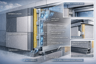
Continuous insulation (CI) was supposed to solve a predictable problem: thermal bridging through studs, shelf angles, and structural penetrations. By wrapping the building with an uninterrupted layer of insulation, designers could meaningfully increase whole-wall R-values, reduce condensation risk, and simplify compliance with increasingly stringent energy codes.
In energy models, it works beautifully.
In the field, it often does not.
Facade engineers and energy consultants are increasingly encountering a gap between modeled performance and post-construction outcomes. Whole-wall R-values that appeared conservative in the energy model are not materializing in thermographic scans, enclosure commissioning, or energy-use intensity tracking. As codes tighten and carbon reporting requirements expand, those discrepancies are no longer academic—they are contractual exposure points.
The issue is not that continuous insulation is conceptually flawed. The issue is that the details required to make it perform are frequently compromised by attachment systems, cladding supports, sequencing decisions, and structural realities that are insufficiently represented in simplified thermal models.
This is where thermal continuity moves from a compliance exercise to a risk management issue.
Whole-Wall R-Value: What the Model Assumes
Whole-wall R-value calculations are intended to account for more than just cavity insulation. They incorporate framing factors, sheathing, cladding attachments, and interior finishes. In principle, this produces a realistic representation of in-service performance.
But most project energy models still rely on assumptions that are cleaner than the field reality:
- Idealized attachment spacing
- Limited thermal bridging through fasteners
- Uniform insulation thickness
- No compression or voids
- Minimal thermal bypass at transitions
Even advanced 2D modeling underestimates three-dimensional heat flow effects at corners, slab edges, parapets, and window interfaces. When attachment systems are simplified or treated as negligible, the model produces R-values that assume continuity that does not exist.
In practice, the cladding support system often governs thermal performance more than the insulation layer itself.
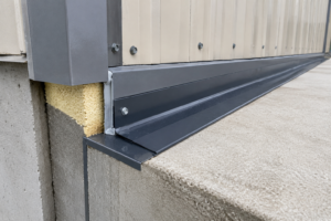
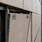
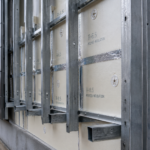
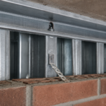
Attachment Systems: The Hidden Thermal Bridge
The most common divergence between modeled and field performance occurs at the attachment system.
Cladding supports—whether steel girts, aluminum rails, clip-and-rail systems, masonry anchors, or structural shelf angles—introduce highly conductive elements that interrupt the insulation plane. Even “thermally broken” systems still create point or linear bridges that must be quantified accurately.
A few recurring realities:
1. Linear Metal Girts
Continuous steel Z-girts running horizontally across insulation can reduce effective R-value dramatically. Depending on spacing and gauge, reductions of 30–50 percent from nominal insulation values are not uncommon.
Many models treat girts as discrete components. In reality, they behave as repeating thermal highways.
2. Fastener Density
Fasteners are often dismissed as negligible. In low-density conditions, they may be. But in high-load facade systems—especially high-rise applications—fastener counts increase significantly. Stainless steel or carbon steel fasteners penetrating thick CI layers can meaningfully reduce effective performance.
The impact compounds with thicker insulation.
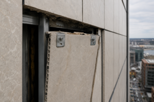
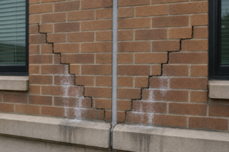
3. Shelf Angles and Slab Edge Conditions
Shelf angles interrupt CI at every floor line in masonry veneer assemblies. If not thermally broken or structurally offset, they create linear bridges that are often underrepresented in energy models.
At slab edges, insulation continuity becomes geometrically complex. Small discontinuities create disproportionately large heat flow effects due to 3D thermal bridging.
In many cases, the largest thermal losses occur precisely where the model assumes continuity.
Sequencing Decisions That Compromise Continuity
Even when attachment systems are well-designed, sequencing can undermine performance.
Compression and Deformation
Mineral wool and semi-rigid boards are frequently compressed by rails and brackets during installation. Compression reduces effective thickness and alters thermal performance. While the material may retain nominal R-value per inch in laboratory testing, in-service compression reduces overall performance.
Installers are not modeling thermal continuity—they are solving alignment and structural tolerances.
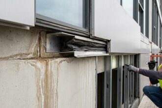
Misaligned Planes
Air barrier installation frequently precedes cladding attachment. If the CI layer is uneven, improperly fastened, or adjusted in the field to accommodate tolerance issues, gaps can form at transitions.
Small gaps can create convective looping and thermal bypass, especially in ventilated rain-screen systems.
Field Modifications
Value engineering substitutions frequently alter:
- Attachment spacing
- Rail depth
- Insulation type
- Fastener material
Unless these changes trigger a revised thermal analysis, the project may continue to rely on outdated modeled values.
This is not an uncommon litigation pathway: the building was modeled correctly for a system that was never installed.
The 2D vs. 3D Modeling Problem
Most energy compliance workflows rely on 1D or 2D assumptions embedded in software tools. These approaches are efficient but struggle with:
- Balcony penetrations
- Parapet transitions
- Curtain wall anchors
- Complex bracket geometries
True 3D finite element modeling provides more accurate results, but it is time-intensive and rarely performed outside of high-performance or institutional projects.
As a result, critical details are often approximated.
For facade engineers, this presents a practical question: which details warrant 3D analysis, and which can reasonably rely on simplified assumptions?
Increasingly, the answer is tied to risk tolerance rather than pure energy modeling.
Thermal Performance vs. Structural Demand
There is an inherent tension between structural capacity and thermal continuity.
Thicker insulation increases eccentricity of loads on attachment brackets. As insulation depth grows to meet aggressive energy targets, attachment systems must carry greater bending moments.
Design responses often include:
- Thicker metal
- Reduced bracket spacing
- Increased fastener count
Each structural improvement potentially increases thermal bridging.
Without integrated analysis between structural and thermal design teams, performance degrades incrementally.
This coordination gap is rarely visible in energy models but clearly visible in infrared scans after occupancy.
Air Leakage: The Multiplier Effect
Even perfectly modeled CI loses effectiveness if air leakage pathways exist.
Energy models frequently treat conductive and convective losses separately. In the field, they interact.
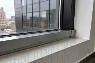
Small discontinuities in air barrier continuity—particularly at transitions between wall, roof, and foundation—can allow air movement that bypasses insulation entirely. The result is effective R-values far below modeled values.
Continuous insulation does not compensate for discontinuous air control layers.
Facade engineers evaluating underperformance should always consider whether air leakage, not just conduction, is contributing to discrepancies.
Why This Is Becoming a Contractual Risk
Stricter energy codes and carbon reporting frameworks are elevating envelope performance from a compliance checkbox to a measurable deliverable.
When projects commit to:
- Targeted EUI reductions
- Operational carbon benchmarks
- Performance-based incentives
- LEED or other certification metrics
Modeled thermal performance becomes embedded in contractual expectations.
If actual performance diverges meaningfully, stakeholders begin asking difficult questions:
- Was the attachment system modeled accurately?
- Were substitutions reviewed thermally?
- Did construction sequencing alter performance?
- Was commissioning sufficient to verify installation quality?
The liability exposure does not rest solely with one party. Architects, facade engineers, energy modelers, contractors, and manufacturers all intersect at the point where design intent meets installation reality.
Continuous insulation underperformance is no longer just a technical issue—it is a documentation and verification issue.
Common Mistakes in CI Specification and Review
Across projects, several patterns recur:
- Assuming nominal R-value equals effective performance
Insulation thickness alone does not define whole-wall R-value. - Failing to model the actual attachment system
Generic assumptions about “thermally broken” systems are insufficient. - Ignoring slab edge and parapet conditions
Linear bridges at transitions often dominate total losses. - Overlooking fastener impact at high density
Particularly in high-wind or seismic zones. - Not reanalyzing after value engineering changes
Thermal performance should be recalculated whenever the support system changes. - Separating structural and thermal design reviews
Integrated review is essential as insulation thickness increases.
Practical Steps for Facade Engineers and Energy Consultants
To reduce divergence between modeled and field performance:
Model the Actual Attachment Geometry
Even simplified 2D models that incorporate real bracket spacing and metal thickness provide more reliable results than nominal assumptions.
Identify High-Risk Details for 3D Analysis
Balconies, shelf angles, and curtain wall anchors often justify targeted 3D modeling.
Coordinate Early with Structural Teams
Attachment selection should be informed by both load path and thermal impact, not determined sequentially.
Require Recalculation After Substitutions
If the cladding support system changes, thermal modeling should be updated. This should be embedded in submittal review requirements.
Incorporate Envelope Commissioning
Thermography and air leakage testing provide real-world validation and protect all parties by identifying issues early.
The Reality Check
Continuous insulation remains a critical tool for improving building performance. The concept is sound. The physics are clear.
But thermal models represent idealized assemblies. Buildings are constructed through trade coordination, tolerance adjustments, sequencing compromises, and sometimes cost-driven substitutions.
The divergence between modeled and installed performance is not accidental—it is predictable.
For facade engineers and energy consultants, the path forward is not to abandon CI, but to treat thermal continuity as a detail-driven discipline rather than a thickness-driven one.
The question is no longer whether continuous insulation works in theory.
The question is whether the attachment system, sequencing strategy, and verification process allow it to work in practice.
As energy codes tighten and performance commitments become contractual obligations, that distinction will increasingly define both building outcomes and professional risk.